5G UPF: From Flow Steering to Session Affinity
Alexandre Cassen, <acassen@gmail.com>
The previous article covered the hardware foundation by introducing NIC rx_queue pinning, IRQ affinity, range partitioning math, and end-to-end flow steering validation with TC flower rules. Every packet landed on the intended queue, classified entirely by NIC firmware, with zero CPU involvement on the classification path.
But TC flower rules are static, manually installed, and disconnected from the session lifecycle. This article takes the next step by integrating range partitioning into the UPF control plane so that every PFCP session establishment becomes a scheduling decision the NIC enforces at line rate. It introduces GTP-Guard's configuration framework that bridges hardware flow steering and PFCP session management, and provides concrete configuration examples for realistic mobile network deployments.
The Foundation
Three building blocks from the previous article are worth recalling briefly.
NIC rx_queue IRQ pinning. Each rx_queue interrupt is bound to a dedicated data-path core, creating a 1:1 mapping between queue and CPU. On our reference platform this gives 8 queues per port, each served by its own core.
Range partitioning. A W-bit field (32-bit TEID or IP address) is split into N equal
ranges using the top k = log2(N) bits. With 8 queues, k=3, and the mask is 0xe0000000 for
TEIDs or 255.224.0.0 for a /8 IPv4 prefix. Each range maps to one queue.
Flow steering rules. TC flower rules installed in the NIC firmware match each range and assign the packet to the corresponding rx_queue. The CPU never participates in the classification decision.
The combination means that once a session's TEID falls within a specific range, all upstream packets for that session are processed by the same CPU for the entire session lifetime. The same applies downstream through IP sub-prefix partitioning. The remaining question is: who decides which range a new session should allocate from?
Range Partition Configuration
GTP-Guard introduces the range-partition configuration object to define TEID and IP address
pools split into partitions. Each partition corresponds to one slice of the address space and
backs a dedicated allocation pool.
A range-partition has a name and a type. The type can be teid, ipv4, or ipv6. The most
common way to create one is through auto-split, where a single base range and a partition
count generate all sub-ranges automatically.
Auto-split
Auto-split takes a base range and a count (which must be a power of 2) and generates N
partitions using k = log2(count) additional prefix bits. This is the direct software
equivalent of the teid-split and ip-pfx-split tools described in the previous article.
For TEID partitioning, the syntax uses a hex base with a prefix bit count:
range-partition upf-teid
 type teid ipv4
 split 0x00000000/0 count 8
!
This splits the full 32-bit TEID space into 8 equal ranges. Partition 0 covers TEIDs
0x00000000 through 0x1fffffff, partition 1 covers 0x20000000 through 0x3fffffff, and
so on. Each partition holds 536 million TEIDs, more than any single UPF will ever need. The
mask is 0xe0000000, identical to what teid-split 8 produces.
For IPv4:
range-partition upf-ipv4
 type ipv4
 split 10.0.0.0/8 count 8
!
This generates 8 sub-prefixes of /11 each (10.0.0.0/11, 10.32.0.0/11, ...
10.224.0.0/11), with roughly 2 million addresses per partition.
For IPv6:
range-partition upf-ipv6
 type ipv6
 split 2001:db8::/46 count 8
!
This generates 8 /49 sub-prefixes, each containing over 500 trillion addresses.
Manual per-part declaration
When partitions need unequal sizes or non-contiguous ranges, manual declaration is available. The syntax differs by type where IPv4 and IPv6 use CIDR notation, while TEID uses hex base and mask.
range-partition custom-teid
 type teid ipv4
 part-id 0 range 0x10000000 mask 3
 part-id 1 range 0x20000000 mask 3
!

range-partition custom-ipv4
 type ipv4
 part-id 0 prefix 10.0.0.0/11
 part-id 1 prefix 10.32.0.0/11
!
Manual part-id and split are mutually exclusive within a single range-partition. Mixing
them is rejected by the parser.
Operational visibility
The show range-partition command displays expanded per-partition details, even when
auto-split was used:
gtp-guard> show range-partition upf-teid
range-partition upf-teid  type=teid  parts=8  refcnt=1
  split 0x00000000/0 count 8
╭─────────┬──────────────┬───────┬───────────┬────────╮
│ part-id │ base/prefix  │ inuse │     total │ % used │
├─────────┼──────────────┼───────┼───────────┼────────┤
│       0 │ 0x00000000/3 │ 42318 │ 536870912 │  0.01% │
│       1 │ 0x20000000/3 │ 41205 │ 536870912 │  0.01% │
│       2 │ 0x40000000/3 │ 43102 │ 536870912 │  0.01% │
│       3 │ 0x60000000/3 │ 40876 │ 536870912 │  0.01% │
│       4 │ 0x80000000/3 │ 42544 │ 536870912 │  0.01% │
│       5 │ 0xa0000000/3 │ 41890 │ 536870912 │  0.01% │
│       6 │ 0xc0000000/3 │ 43001 │ 536870912 │  0.01% │
│       7 │ 0xe0000000/3 │ 42110 │ 536870912 │  0.01% │
╰─────────┴──────────────┴───────┴───────────┴────────╯
The base/prefix column shows the partition base value followed by the mask-bits count, so
/3 for 8 partitions (k = log2(8) = 3). Each row reports live pool occupancy from
inuse and total.
The show running-config emits only the compact split form when auto-split was used,
keeping configurations readable.
Flow Steering Policy
The flow-steering-policy object binds NIC hardware queue-ids to range-partition part-ids.
It is the configuration-level equivalent of installing TC flower rules via iproute2/tc tool.
It declares which queue handles which partition.
flow-steering-policy upf-steering
 queue-id 0-7
 queue-id bind range-partition upf-teid
 queue-id bind range-partition upf-ipv4
 queue-id bind range-partition upf-ipv6
!
The queue-id command uses the same cpulist-style format familiar from cpumask declarations
(0-7, 0-3,8-11, 0,2,4,6). The binding is positional in ascending order where queue-id 0
maps to part-id 0, queue-id 1 maps to part-id 1, and so on. Multiple range-partitions of
different types can be bound in the same policy, one per type.
If the queue-id count and part-id count differ, GTP-Guard emits a warning but accepts the
configuration. At runtime only min(nr_queue_ids, nr_parts) mappings are active.
The policy is then attached to a network interface:
interface p0
 flow-steering-policy upf-steering
!
GTP-Guard validates that the configured queue-ids exist on the physical interface. If any queue-id exceeds the interface's actual rx_queue count, a warning is emitted. The configuration is still accepted because hardware topology can change on NIC reconfiguration.
CPU Scheduling Group
The cpu-sched-group defines a set of eligible CPUs, a scheduling algorithm, and optional
per-CPU weights. It is the entry point for the scheduling decision. When a new PFCP session
arrives, the group's algorithm elects which CPU will handle it.
Range-partition binding extends the scheduling group by mapping each CPU in the cpumask to a partition index:
cpu-sched-group dp-plane
 cpumask 0-7
 algorithm wlc
 cpumask bind range-partition upf-teid
 cpumask bind range-partition upf-ipv4
 cpumask bind range-partition upf-ipv6
!
The binding follows the same positional logic as flow-steering-policy with CPU 0 (first in cpumask) maps to part-id 0, CPU 1 maps to part-id 1, and so on. Multiple range-partitions of different types can be bound, one per type.
The result is a complete chain where the scheduling algorithm elects CPU N, which means partition N, which determines the TEID range and IP sub-prefix for the session. The NIC flow steering rules guarantee that all traffic matching those ranges reaches CPU N.
Available scheduling algorithms
GTP-Guard provides a range of algorithms inspired by the IPVS/LVS tradition (Wensong Zhang, if you are reading these lines, this is one is dedicated to you my freind ;) back in time while hacking LVS in late 2000's). The connection-based family uses session count as the primary metric:
| Algorithm | Description |
|---|---|
| rr | Round-robin rotation across eligible CPUs |
| wrr | Weighted round-robin proportional to per-CPU capacity weights |
| lc | Least-connection: fewest active PFCP sessions |
| wlc | Weighted least-connection: sessions/weight ratio (recommended default) |
| sed | Shortest expected delay: (sessions+1)/weight, avoids idle-CPU starvation |
| nq | Never-queue: picks any idle CPU first, falls back to SED |
The resource-based family uses live per-CPU metrics collected every 200ms:
| Algorithm | Description |
|---|---|
| ll | Least-load: lowest CPU utilization |
| lbw | Least-bandwidth: lowest total bytes per second |
| lpps | Least-PPS: lowest packet rate |
Per-CPU weights allow fine-grained capacity tuning:
cpu-sched-group dp-plane
 cpumask 0-7
 algorithm wlc
 weight cpu 0 100
 weight cpu 1 100
 weight cpu 2 100
 weight cpu 3 100
 weight cpu 4 80
 weight cpu 5 80
 weight cpu 6 60
 weight cpu 7 60
!
A CPU with weight 100 receives roughly twice as many sessions as one with weight 50 under the wlc algorithm. Advanced algorithms covering trend-based scheduling, multi-metric scoring, and constraint-based gating are covered in the companion article 5G UPF: Smart Session Placement.
PFCP Integration
Range partitions are bound at two levels in the PFCP hierarchy: the pfcp-router (global default) and the APN (per-APN override).
pfcp-router binding
The pfcp-router accepts one range-partition per type. These serve as defaults for all APNs handled by this router:
pfcp-router main
 cpu-sched dp-plane
 range-partition upf-teid
 range-partition upf-ipv4
 range-partition upf-ipv6
!
The cpu-sched directive binds the scheduling group to the router. All session establishment
requests received by this router will use dp-plane to elect a CPU, unless the target APN
overrides it.
APN-level override
An APN can override specific types while inheriting the rest from the pfcp-router:
access-point-name internet
 ! inherits all three from pfcp-router
!

access-point-name ims
 cpu-sched dp-ims
 range-partition ims-teid
 range-partition ims-ipv4
 ! overrides cpu-sched, teid, and ipv4; inherits ipv6 from pfcp-router
!
The resolution follows a simple lookup: APN override takes precedence, pfcp-router provides the default. At most one range-partition per type can be bound at each level.
Range-partition and flat IP pool are mutually exclusive per address family on an APN. Configuring both is rejected by the parser.
Allocation flow
When a PFCP Session Establishment Request arrives, the sequence is:
- The cpu-sched algorithm elects a CPU from the scheduling group
- The CPU's position in the cpumask determines the partition index
- TEID allocation resolves the TEID range-partition (APN override or router default) and draws a TEID from the matching partition's pool
- UE IP allocation resolves the IPv4/IPv6 range-partition and draws addresses from the matching partition's pool
- The session is pinned to the elected CPU
From the first data packet onwards, NIC flow steering routes all traffic for this session to the elected CPU. No runtime re-classification or thread migration is needed.
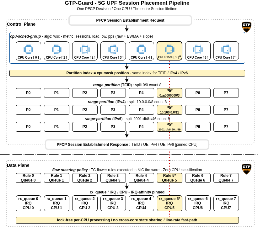
End-to-end session placement pipeline: one PFCP decision pins a session to one CPU for its entire lifetime, across the control plane (TEID and IP allocation) and the data plane (NIC flow steering).
Dual-stack affinity
When a UE session requires both IPv4 and IPv6 addresses, both allocations use the same partition index derived from the elected CPU. This guarantees that downstream traffic for both address families reaches the same rx_queue and the same CPU. Without this constraint, a dual-stack session would split its downstream traffic across two cores, breaking the lock-free processing guarantee and reintroducing cross-core state sharing.
Complete Example: Multi-APN Mobile Network
This section assembles a full end-to-end configuration for a realistic UPF deployment. The hardware is the same dual-socket server from the previous article: 48 cores, 2 ConnectX-7 adapters, 8 rx_queues per port. The operator serves three APNs with different requirements.
The internet APN handles consumer broadband: high throughput, millions of UEs, standard QoS. The ims APN handles VoLTE and VoNR: latency-sensitive, moderate session count, requiring dedicated CPU resources. The iot.m2m APN handles NB-IoT and LTE-M: massive session counts, low per-session throughput.
TEID space division
The 32-bit TEID space is carved into non-overlapping regions, one per APN. This prevents any flow steering ambiguity, because each TEID range maps to exactly one APN's CPU group.
range-partition teid-internet
 type teid ipv4
 split 0x00000000/1 count 8
!
range-partition teid-ims
 type teid ipv4
 split 0x80000000/2 count 4
!
range-partition teid-iot
 type teid ipv4
 split 0xc0000000/2 count 4
!
The internet APN takes the lower half of the TEID space (0x00000000-0x7fffffff), split
into 8 partitions of 256 million TEIDs each. The IMS APN takes the third quarter
(0x80000000-0xbfffffff), split into 4 partitions. The IoT APN takes the fourth quarter
(0xc0000000-0xffffffff), also 4 partitions. No overlap, no ambiguity.
IP pool partitions
Each APN uses its own IP address space:
range-partition ipv4-internet
 type ipv4
 split 10.0.0.0/8 count 8
!
range-partition ipv4-ims
 type ipv4
 split 172.16.0.0/16 count 4
!
range-partition ipv6-internet
 type ipv6
 split 2001:db8::/46 count 8
!
The internet APN splits 10.0.0.0/8 into 8 sub-prefixes of /11, each covering roughly
2 million addresses. The IMS APN splits 172.16.0.0/16 into 4 sub-prefixes of /18, each
covering 16K addresses, which is sufficient for the lower session volume of voice traffic.
Flow steering policies
flow-steering-policy fs-internet
 queue-id 0-7
 queue-id bind range-partition teid-internet
 queue-id bind range-partition ipv4-internet
 queue-id bind range-partition ipv6-internet
!
flow-steering-policy fs-ims
 queue-id 0-3
 queue-id bind range-partition teid-ims
 queue-id bind range-partition ipv4-ims
!
flow-steering-policy fs-iot
 queue-id 0-3
 queue-id bind range-partition teid-iot
!

interface p0
 flow-steering-policy fs-internet
 flow-steering-policy fs-ims
 flow-steering-policy fs-iot
!
CPU scheduling groups
Each APN gets its own scheduling group on dedicated cores:
cpu-sched-group dp-internet
 cpumask 0-7
 algorithm lc
 cpumask bind range-partition teid-internet
 cpumask bind range-partition ipv4-internet
 cpumask bind range-partition ipv6-internet
!
cpu-sched-group dp-ims
 cpumask 24-27
 algorithm sed
 cpumask bind range-partition teid-ims
 cpumask bind range-partition ipv4-ims
!
cpu-sched-group dp-iot
 cpumask 28-31
 algorithm lc
 cpumask bind range-partition teid-iot
!
The internet group spans CPUs 0-7 on NUMA node 0 and uses LC to balance sessions purely by count, since all eight cores share the same capacity. The IMS group uses CPUs 24-27 on NUMA node 1 with SED (shortest expected delay) to spread sessions evenly during ramp-up, avoiding idle-CPU starvation on latency-sensitive voice traffic. The IoT group uses CPUs 28-31, also with LC, because IoT sessions generate negligible per-session traffic but accumulate in large numbers.
PFCP router and APN binding
access-point-name internet
 ! inherits everything from pfcp-router
!
access-point-name ims
 cpu-sched dp-ims
 range-partition teid-ims
 range-partition ipv4-ims
!
access-point-name iot.m2m
 cpu-sched dp-iot
 range-partition teid-iot
!
pfcp-router main
 cpu-sched dp-internet
 range-partition teid-internet
 range-partition ipv4-internet
 range-partition ipv6-internet
!
How cpu-sched and range-partition fit together
The two bindings are complementary. The cpu-sched group runs the scheduling
algorithm and elects a CPU ID for the new session. That CPU's position inside
the group's cpumask then becomes the partition index passed to every bound
range-partition (TEID, IPv4, IPv6) as the allocation key. Each range-partition
draws its resource from the matching slice, so the elected CPU, the TEID range,
and the IP sub-prefix are all aligned by construction. NIC flow steering then
routes every packet matching those ranges back to the same CPU.
The internet APN inherits all bindings from the pfcp-router. The IMS APN overrides the scheduling group and the TEID/IPv4 partitions, while inheriting the IPv6 partition from the router level. The IoT APN overrides the scheduling group and the TEID partition only. It has no IP range-partition, so it uses a flat IP pool for address allocation. This is a deliberate choice: IoT devices produce too little traffic for IP-based flow steering to provide any measurable benefit. The TEID partition still matters because it keeps IoT sessions on their dedicated CPUs.
The Session Lifecycle
Consider a subscriber attaching to the internet APN. The SMF sends a PFCP Session Establishment Request to the UPF.
- GTP-Guard resolves the APN (
internet) and finds no cpu-sched override, so it uses the pfcp-router default:dp-internet - The LC algorithm inspects per-CPU session counts and elects CPU 3 (fewest active sessions)
- CPU 3 is the 4th position (index 3) in the cpumask
0-7 - TEID allocation resolves
teid-internetand draws a TEID from partition 3 (range0x30000000-0x3fffffff). It returns TEID0x30000042 - IPv4 allocation resolves
ipv4-internetand draws an address from partition 3 (range10.96.0.0/11). It returns10.100.23.17 - IPv6 allocation resolves
ipv6-internetand draws an address from partition 3 (range2001:db8:1:8000::/49). It returns2001:db8:1:8042::1 - The session is created with
cpu=3
From the very first data packet, the NIC firmware enforces the placement. Every GTP-U
upstream packet carrying TEID 0x30000042 matches the flow steering rule
enc_key_id 0x30000000/0xf0000000 and lands on rx_queue 3, which fires its IRQ on CPU 3.
Every downstream IPv4 packet destined for 10.100.23.17 matches the rule
dst_ip 10.96.0.0/255.224.0.0 and also lands on rx_queue 3. Both directions, same CPU, same
queue, same UE context shard. No locks, no cross-core coordination, for the entire session
lifetime.
Now consider a VoLTE subscriber on the IMS APN. The same sequence runs, but the APN override
kicks in so the scheduling group is dp-ims, the TEID partition is teid-ims, and the IPv4
partition is ipv4-ims. SED elects CPU 25 (index 1 in cpumask 24-27). The TEID comes from
partition 1 of teid-ims (range 0x90000000-0x9fffffff), and the IPv4 address comes from
partition 1 of ipv4-ims (range 172.16.64.0/18). This session runs on an entirely separate
CPU, separate TEID range, and separate IP pool, fully isolated from consumer broadband
traffic.
Monitoring the result
The show cpu-sched command provides real-time visibility:
gtp-guard> show cpu-sched dp-internet
CPU Scheduling Group: dp-internet (algorithm: lc)
  CPU   Weight   Sessions   Load   Load~   BW(Mbps)   BW~(Mbps)       PPS      PPS~
    0      100       4231   0.23    0.22      850.2       812.4    125430    121200
    1      100       4158   0.21    0.20      790.1       801.3    118200    119500
    2      100       4302   0.24    0.23      870.5       855.0    131000    128400
    3      100       4089   0.19    0.20      720.3       735.8    108700    110500
    4      100       4244   0.22    0.22      840.0       830.2    124800    123100
    5      100       4190   0.20    0.21      800.4       795.5    120100    119800
    6      100       4311   0.23    0.23      860.1       858.0    129400    128700
    7      100       4110   0.21    0.21      780.8       782.1    117600    118000

gtp-guard> show cpu-sched dp-ims
CPU Scheduling Group: dp-ims (algorithm: sed)
  CPU   Weight   Sessions   Load   Load~   BW(Mbps)   BW~(Mbps)       PPS      PPS~
   24      100        312   0.08    0.08       42.1        41.5      6200      6150
   25      100        308   0.07    0.07       39.8        40.2      5900      5950
   26      100        315   0.09    0.08       43.5        42.8      6400      6310
   27      100        305   0.06    0.07       38.2        38.9      5700      5780
The internet group shows a nearly uniform session distribution across 8 CPUs, each handling
around 4200 sessions at 20-24% load, reflecting the straightforward session-count balancing
of LC. The IMS group shows a much lighter load, as expected for voice traffic, with SED
keeping the session count tightly balanced across 4 CPUs. The Load~, BW~(Mbps), and
PPS~ columns are the EWMA-smoothed counterparts of the raw values, useful to spot
sustained trends while filtering transient bursts.
What Comes Next
The scheduling algorithms presented so far (wlc, sed, lc) operate on a single metric. They work well for uniform workloads, but fall short when different bottlenecks coexist. A CPU can sit at low utilization while saturating its NIC queue bandwidth. Session count says nothing about per-session traffic volume.
The companion article 5G UPF: Smart Session Placement introduces advanced scheduling algorithms that address these limitations: trend-based algorithms that detect load trajectory, a Weighted Score Composite that blends multiple metrics into a single score, and a Constraint-Based Scheduler that enforces hard limits before delegating to any other algorithm. Together they give operators fine-grained control over session placement quality and SLA differentiation.